
Live-Sky Anti-Jamming Antenna Testing puts the antenna where it will actually operate: under real satellites, real multipath, and real interference. Unlike a shielded lab or a quiet chamber, the live sky does not pause for calibration. It brings changing geometry, atmospheric effects, and unpredictable RF traffic into the measurement.
This field guide walks through seven steps that make live-sky testing useful instead of merely anecdotal. It also shows where live-sky work fits alongside GNSS anti-jamming testing and jamming simulation.
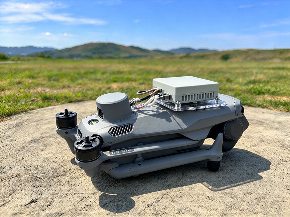
Why Live-Sky Anti-Jamming Antenna Testing Matters
A chamber can repeat a scenario. The live sky can reveal whether that scenario resembles reality.
Live-Sky Anti-Jamming Antenna Testing captures antenna gain, phase behavior, and nulling performance in the presence of real satellite motion. It also exposes installation effects that bench testing often misses, such as cable routing, ground plane size, and nearby structures.
Live-Sky Anti-Jamming Antenna Testing vs. Chamber Testing
The two approaches answer different questions. The table below compares them without treating one as a replacement for the other.
| Aspect | Live-Sky Testing | Chamber Testing |
|---|---|---|
| RF environment | Uncontrolled, real-world | Controlled, repeatable |
| Satellite geometry | Naturally changing | Scripted |
| Multipath | Real and site-specific | Limited or modeled |
| Interference | Opportunistic or injected | Precise and repeatable |
| Cost | Lower setup, higher variability | Higher setup, lower variability |
| Best use | Validation and anomaly discovery | Threshold and regression testing |
A practical program uses both. Chamber data establishes repeatable limits. Live-sky data confirms that those limits survive contact with the real world.
7 Steps for Live-Sky Anti-Jamming Antenna Testing
The following sequence keeps the test grounded. Each step produces evidence that the next step can use.
Step 1: Define the Antenna Under Test
Record the antenna type, gain pattern, polarization, mounting interface, and feed network. For CRPA systems, note element count, calibration method, and beamforming mode.
Step 2: Choose a Representative Site
The site should match the intended installation. A rooftop, vehicle roof, or mast can produce very different results. Document nearby reflectors, transmitters, and obstructions.
Step 3: Establish a Clean Baseline
Before any jammer appears, log satellite visibility, C/N0, position residuals, and AGC levels. This baseline becomes the reference for every later comparison.
Step 4: Monitor the RF Spectrum
Use a spectrum analyzer or SDR to record the ambient RF floor. Note cellular, Wi-Fi, and other out-of-band energy that could affect the front end.
Step 5: Introduce Controlled Interference
If regulations allow, inject a known interference source at a safe distance and power level. Otherwise, wait for opportunistic interference and document it carefully.
Step 6: Capture Antenna and Receiver Response
Log beamforming weights, null depth, C/N0 degradation, tracking status, and position error. For array antennas, record the direction of arrival if available.
Step 7: Repeat and Compare
Run the same route or static setup multiple times. Compare results across time, weather, and satellite geometry. A single live-sky run is an observation, not a conclusion.
Key Metrics in Live-Sky Anti-Jamming Antenna Testing
Metrics turn field observations into engineering decisions. The table below lists the most useful ones.
| Metric | What It Reveals | Practical Note |
|---|---|---|
| C/N0 per satellite | Tracking margin | Compare against baseline, not absolute value |
| AGC level | Front-end stress | Sudden jumps may indicate interference |
| Null depth | Spatial rejection | Direction and bandwidth matter |
| Position error growth | Navigation impact | Horizontal and vertical separately |
| Time to loss of lock | Threshold under interference | Depends on satellite geometry |
| Recovery time | Resilience after interference | Test after the source stops |
| False lock rate | Spoofing or confusion risk | Critical for safety-related use |
For civil and safety work, ITU recommendations may also shape acceptable interference levels.
Common Pitfalls in Live-Sky Anti-Jamming Antenna Testing
-
Treating one live-sky run as a complete validation.
-
Ignoring site-specific multipath.
-
Comparing antennas on different days without geometry context.
-
Using a spectrum analyzer without enough dynamic range.
-
Forgetting to log receiver firmware and configuration.
-
Testing only a static mount when the real use is mobile.
-
Recording interference without checking local regulations.
-
Skipping post-test calibration checks.
Each pitfall can create a false conclusion. A structured log and repeated runs reduce that risk.
FAQ: Live-Sky Anti-Jamming Antenna Testing
Is live-sky testing better than chamber testing?
Neither is universally better. Live-sky testing adds realism; chamber testing adds repeatability. Use both.
Can I test anti-jamming antennas without a licensed jammer?
Yes, but you may need to rely on ambient interference or authorized test transmitters. Always check local rules first.
How long should a live-sky test run?
Long enough to capture satellite geometry changes and several interference events. A few hours is often a minimum for static tests.
What equipment is needed?
A reference receiver, spectrum analyzer or SDR, logging computer, and a safe mounting system. A GNSS simulator can help prepare scenarios before going outside.
Final Thoughts on Live-Sky Anti-Jamming Antenna Testing
Live-Sky Anti-Jamming Antenna Testing is the bridge between controlled lab results and operational trust. It will not replace chamber testing or simulation, but it will expose the installation effects, multipath, and real interference that those methods cannot fully reproduce. Define the antenna, pick a representative site, baseline carefully, monitor the spectrum, inject or observe interference, capture the response, and repeat. That discipline turns live-sky work from a gamble into evidence.