
If you buy anti-jamming modules for a defense, UAV, GNSS timing, or communications platform, you already know off-the-shelf rarely fits. The OEM customization process is less about picking a box and more about translating a messy RF environment into a manufacturable module.
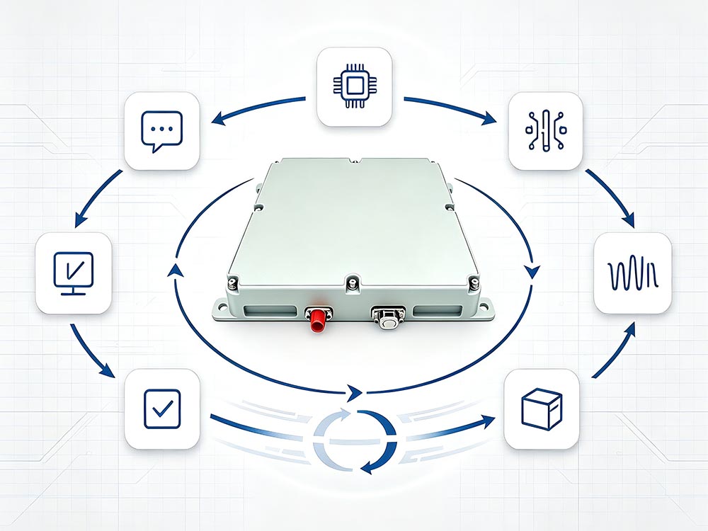
That translation takes discipline. Miss one detail—an interface, a thermal limit, a jamming scenario—and the project can stall in integration. The guide below breaks the process into practical stages, with the tables and checkpoints that keep a custom anti-jamming module project moving.
Why OEM Customization Is Not a Catalog Order
Catalog modules are built for the widest possible market. That means compromises: fixed frequency bands, standard connectors, limited filtering, and firmware you cannot touch. On a real platform, those compromises show up as interference, thermal issues, or an integration headache.
OEM customization exists because anti-jamming performance is system-level. The antenna, cable loss, mounting location, power rail, and software all affect results. A module that performs well on a bench may fail once it is bolted into a crowded airframe.
The Anti-Jamming Module OEM Customization Process at a Glance
| Stage | What Happens | Main Deliverable | Typical Duration |
|---|---|---|---|
| Requirements capture | RF threat review, platform constraints, interface needs | Requirements document | 1–2 weeks |
| Feasibility and architecture | RF front-end, filtering, FPGA, algorithm trade-offs | Block diagram and risk list | 2–4 weeks |
| Prototype design | Schematic, PCB, firmware, mechanical layout | Working prototype units | 6–12 weeks |
| Integration and tuning | Interface checks, thermal work, EMC, algorithm tuning | Integration test report | 4–8 weeks |
| Validation | Jamming scenarios, environmental tests, compliance | Qualification report | 4–10 weeks |
| Pilot build | Fixtures, test scripts, yield review | Pilot batch and ATP data | 4–8 weeks |
| Production and lifecycle | BOM control, obsolescence plan, support | Production units | Ongoing |
Timelines shift with complexity. A board-level GNSS anti-jamming module with a standard interface moves faster than a ruggedized multi-band system with custom algorithms and MIL-STD testing.
Stage 1: Put the RF Environment on Paper
Before anyone talks about hardware, collect the facts. The supplier needs more than “we need anti-jamming.”
| Input | Why It Matters | Example |
|---|---|---|
| Threat signals | Sets filtering, dynamic range, and algorithm needs | Continuous-wave, sweep, pulsed, spoofing |
| Operating bands | Defines RF chain and antenna requirements | L1, L2, L5, S-band, custom |
| Antenna | Affects gain, phase matching, and isolation | CRPA, fixed array, single element |
| Platform constraints | Limits size, weight, power, and mounting | UAV bay, vehicle roof, handheld |
| Interfaces | Drives firmware and connector choices | UART, SPI, Ethernet, CAN, PCIe |
| Power and thermal | Prevents overheating and voltage drops | 5 V, 12 V, 28 V, PoE |
| Environmental | Determines enclosure and materials | -40°C to +85°C, IP67, vibration |
| Compliance | Avoids late-stage redesign | MIL-STD, CE, FCC, DO-160 |
| Volume | Shapes tooling, testing, and unit cost | Prototype, low-rate, mass production |
If the threat list is vague, ask for a site survey or field data. “We get interference sometimes” is not a specification.
Stage 2: Feasibility and RF Architecture
Not every requirement can coexist. A module that covers L1, L2, and L5 with high dynamic range, 100 dB isolation, and 10 W power in a 40 mm × 40 mm envelope is not a design—it is a wish list. The supplier should map trade-offs clearly.
Common trade-offs include:
-
Filtering vs. insertion loss
-
Gain vs. noise figure
-
Size vs. channel-to-channel isolation
-
Power consumption vs. thermal headroom
-
Algorithm complexity vs. FPGA resources
-
Ruggedization vs. weight and cost
This is also the stage to settle algorithm ownership. Adaptive filtering, null steering, and beamforming may be supplier IP, customer IP, or licensed from a third party. Put it in writing before PCB layout starts.
Stage 3: Prototype Design and Integration
Once the architecture is fixed, the project moves into hardware and firmware. Customization can touch nearly every part of the module.
| Customization Area | Typical Options | What It Affects |
|---|---|---|
| Frequency | L1/L2/L5, S-band, custom bands | Filters, LO, antenna |
| Form factor | Board-level, module, rugged enclosure | Mounting, serviceability |
| RF interface | SMA, SMPM, MCX, custom | Cable loss, mating cycles |
| Digital interface | UART, SPI, Ethernet, CAN, PCIe | Firmware, host integration |
| Power | 5 V, 12 V, 28 V, PoE | Regulators, heat, protection |
| Algorithms | Adaptive filtering, nulling, beamforming | FPGA load, performance |
| Environmental | IP67, conformal coat, MIL-STD | Materials, testing, cost |
Prototype units should be built with production intent. Hand-modified boards are useful for proof of concept, but they hide manufacturing problems that appear later.
Stage 4: Validation That Matches the Real World
Datasheet numbers are a starting point. Real validation uses conducted jamming, radiated jamming, live-sky signals, dynamic scenarios, EMC checks, and environmental stress. If the supplier only tests with a signal generator on a bench, ask why.
A strong validation plan includes:
-
Conducted and radiated jamming tests
-
Live-sky GNSS or communication link tests
-
Dynamic platform motion
-
Thermal soak and cold start
-
Vibration and shock, if required
-
EMI/EMC pre-compliance
-
Acceptance test limits for production
The goal is not just to prove the module works. It is to prove it works in the same conditions your platform will see.
Stage 5: Pilot Build, Production, and Lifecycle
Pilot build is where lab success meets manufacturing reality. Look for design-for-manufacture feedback, test fixtures, automated test procedures, yield data, and a clear BOM control process.
Ask about critical components early. RF parts, FPGAs, and specialty connectors can have long lead times or obsolescence risk. A good OEM partner will propose second sources or form-fit-function alternatives before production, not after.
How to Choose an OEM Partner
| Question | Why It Matters |
|---|---|
| Have you built a module for a similar RF environment? | Past performance reduces technical risk |
| Do you own the algorithm IP? | Avoids licensing surprises |
| What test data will you share? | Shows confidence and traceability |
| How do you handle obsolescence? | Protects long-term supply |
| Do you assemble in-house? | Affects quality control and lead time |
| What is your minimum order? | Aligns with pilot and production plans |
Do not choose on price alone. The cheapest quote often excludes testing, documentation, or the engineering time needed to make the module work in your system.
Common Pitfalls
-
Specifying only frequency, not the actual threat.
-
Leaving compliance and environmental testing to the end.
-
Forgetting thermal design in sealed enclosures.
-
Skipping a written acceptance test plan.
-
Relying on a single-source critical component.
-
Underestimating host interface and firmware integration.
-
Treating the antenna as an afterthought.
Quick Buyer’s Checklist
| Item | Check |
|---|---|
| RF threat list | Documented and prioritized |
| Operating bands | Confirmed with antenna plan |
| Mechanical envelope | Measured, not estimated |
| Power and thermal | Worst-case conditions defined |
| Digital interface | Protocol and pinout agreed |
| Compliance | Standards listed before design |
| Test plan | Conducted, radiated, environmental |
| Acceptance criteria | Pass/fail limits written |
| Production volume | Pilot and steady-state forecast |
| Lifecycle support | Obsolescence and repair plan |
FAQ
How long does anti-jamming module OEM customization take?
Most projects run 3–9 months from requirements to pilot, depending on complexity, compliance, and whether algorithms need changes.
What drives cost?
NRE, RF testing, ruggedization, algorithm licensing, certification, and production volume are the main cost drivers.
Can firmware be customized?
Yes. Interface protocols, filtering thresholds, logging, and update paths are common customization points.
Final Take
The best anti-jamming module OEM customization process is front-loaded. Get the RF environment, interfaces, thermal limits, and test plan clear before design starts. Then choose a partner who can show real test data, control the supply chain, and support the module after production.
That approach does not just produce a custom anti-jamming module. It produces one that survives integration.