
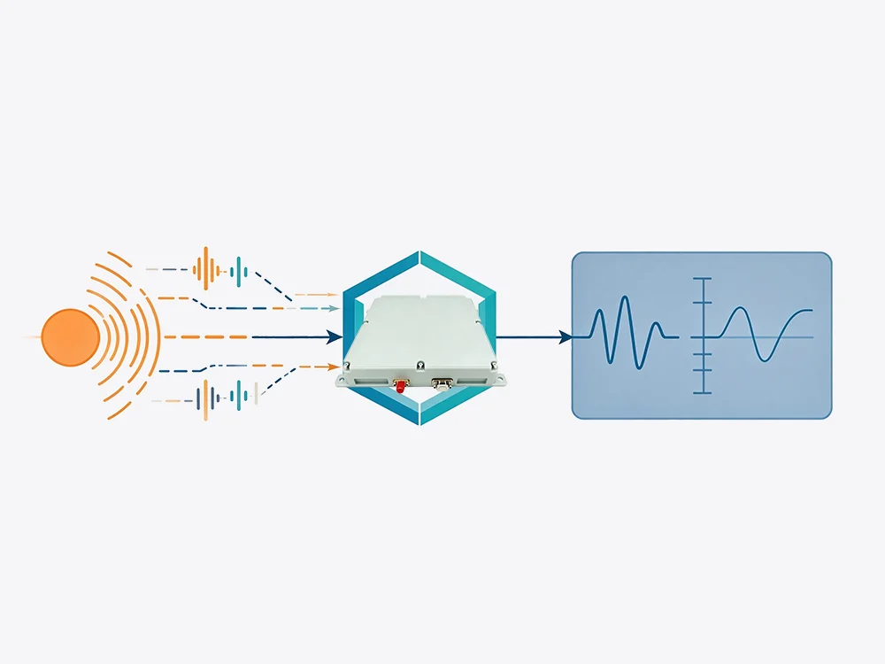
Anti-jamming modules are used in GNSS receivers, UAVs, defense radios, and timing systems. But a claim like “40 dB jamming suppression” means little unless it comes from a controlled, repeatable test. This guide explains how to test anti-jamming module performance from threat model to final report.
1. Define the threat model first
Before connecting instruments, define what the module must survive. Anti-jamming performance depends on jammer type, frequency, power, direction, bandwidth, and duration. A module that rejects one narrowband tone may fail against wideband noise or multiple directional jammers.
| Test dimension | Questions to answer | Example |
|---|---|---|
| Jammer type | Noise, CW, swept, pulsed, or multi-tone? | Wideband noise, 10 MHz bandwidth |
| Frequency | Which bands must be protected? | GNSS L1/L2, 1.2–1.6 GHz |
| Power | What J/S range is required? | 0 to 60 dB |
| Direction | Single or multiple angles? | One jammer at 30°, two at 0°/90° |
| Duration | Continuous or intermittent? | 60 s continuous, 1 µs pulses |
2. Choose conducted or over-the-air testing
Conducted testing is usually better for repeatability and early design validation. Over-the-air (OTA) testing is essential when the antenna, radome, or installation affects performance.
| Method | Best for | Advantages | Limits |
|---|---|---|---|
| Conducted | Module-level validation | Repeatable, lower cost, easy calibration | Ignores antenna and platform effects |
| OTA | Integrated system testing | Captures beamforming, nulling, and coupling | Chamber cost, complex calibration |
| Hybrid | Design and verification | Combines repeatability with real-world effects | Requires careful correlation |
3. Calibrate the RF path before testing
Use a power meter and spectrum analyzer to measure actual power at the DUT input, not at the signal generator output. Document cable loss, attenuator values, combiner loss, and simulator settings. For OTA tests, validate chamber quiet zones and field uniformity.
A basic setup may include:
-
GNSS simulator or signal source
-
Jammer generator
-
Combiner and attenuators
-
Shielded box or anechoic chamber
-
Spectrum analyzer and power meter
-
DUT control and data logging PC
4. Run the core performance tests
The exact test plan depends on the module, but most anti-jamming evaluations should include the following.
| Test | Procedure | Primary metric | Example pass criterion |
|---|---|---|---|
| Baseline | No jammer; record C/N0, TTFF, accuracy | C/N0, TTFF, RMS error | C/N0 within 1 dB of reference |
| J/S threshold | Step jammer power until loss of lock | J/S at loss, recovery time | Maintains lock at J/S 30 dB; recovers <2 s |
| Null depth | Rotate jammer or DUT in chamber | Null depth, angular width | ≥20 dB null at jammer angle |
| Frequency sweep | Sweep jammer across band | Lock status vs frequency | No dropout across L1 band |
| Dynamic jammer | Pulse or sweep jammer | Reacquisition time | Reacquisition <5 s |
| Multi-jammer | Two or three sources | Position error, lock status | Horizontal error <10 m RMS |
5. Track the metrics that matter
Do not rely on a single pass/fail number. A strong anti-jamming test report includes:
-
J/S ratio at loss of lock
-
C/N0 degradation
-
TTFF and reacquisition time
-
Position error: RMS and 95th percentile
-
Null depth and angular coverage
-
Recovery time after jamming stops
-
False lock or false alarm rate
6. Use a scorecard and statistics
Run at least five to ten repeats per condition. Keep satellite geometry, temperature, and cable routing consistent. Then compare results against defined limits.
| Metric | Baseline | With jammer | Pass criterion | Result |
|---|---|---|---|---|
| C/N0 | 45 dB-Hz | 38 dB-Hz | ≥35 dB-Hz | Pass |
| TTFF | 28 s | 42 s | ≤60 s | Pass |
| Horizontal error | 1.8 m RMS | 4.6 m RMS | ≤5 m RMS | Pass |
| Recovery time | — | 1.4 s | ≤2 s | Pass |
| Null depth | — | 24 dB | ≥20 dB | Pass |
7. Avoid common test errors
-
Measuring power at the generator instead of the DUT input
-
Ignoring cable, splitter, and chamber losses
-
Testing only one jammer angle
-
Skipping the no-jamming baseline
-
Using too few repeat runs
-
Forgetting firmware version and DUT settings
-
Testing only at room temperature
8. Document and report
A useful report should include the test setup diagram, equipment calibration dates, DUT serial number, firmware version, environmental conditions, and measurement uncertainty. This makes the result repeatable and defensible.
Conclusion
Testing anti-jamming module performance is a measurement discipline. Start with a clear threat model, calibrate the RF path, establish a baseline, stress the module with repeatable jammers, and quantify J/S, nulling, recovery, and position accuracy. That turns marketing numbers into engineering evidence.