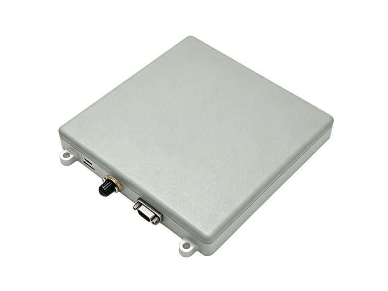
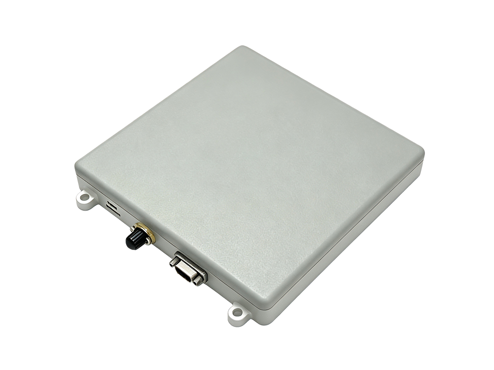
If you are working with UAVs, electronic countermeasure systems, or communication base stations operating in signal-dense areas, you already know the problem. GNSS receivers are vulnerable. A single cheap jammer can knock out positioning. The dual-band four-element anti-jamming antenna from the BNTDFE4A series addresses this directly by combining the antenna array, anti-jamming processor, and navigation receiver into one compact unit.
This is not a lab prototype. It is a production-ready module measuring 170×150×20 mm and weighing 670 grams. It works across two frequency groups: BDS-B1, GPS-L1, Galileo-E1 on the first band, and BDS-B3 on the second. Both bands get independent anti-jamming treatment.
Why the Four-Element Architecture Matters
A single-element GNSS antenna has no spatial filtering capability. It receives everything, including interference. The dual-band four-element anti-jamming antenna uses two groups of four-element arrays. Each group can form spatial nulls toward up to three different interference directions per band, simultaneously.
This means the receiver still gets usable satellite signals even when three jammers are active on each band from different angles. The nulling happens before the signal reaches the Ublox X20P receiver module integrated inside.
For more background on how adaptive nulling works in GNSS arrays, see the overview from the Stanford GPS Lab which covers spatial filtering techniques in detail.
Interference Types Covered
The anti-jamming engine handles broadband, narrowband, pulsed, swept-frequency, and combined jamming patterns. These are the typical waveforms used in denial-of-service attacks against navigation systems. The specification lists single-interference rejection at 110 dB or better, and triple-interference rejection at 95 dB or better.
Power consumption is rated at 18 watts with an input range of 9 to 36 VDC. That is manageable for most UAV power budgets.
Integration and Interfaces
The unit includes an RS422 serial port defaulting to 115200 baud, plus a 3.3V LVTTL UART. Output follows NMEA0183 protocol. A 1PPS output is also available. The connector is a J30J-15ZKP type with a straightforward pinout.
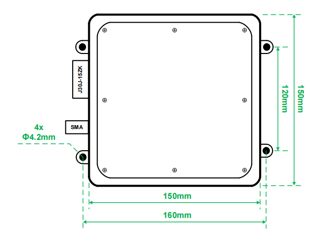
Mounting uses four 4.2 mm through-holes spaced 160 mm by 120 mm. This pattern fits standard drone mounting plates and enclosure brackets.
Interference Rejection Performance
The table above shows the headline numbers. In field terms, a 110 dB single-jammer rejection means the system can maintain positioning even when the jamming signal is 110 dB stronger than the GNSS signal at the antenna input. That is a substantial margin. Three-jammer rejection at 95 dB covers the more realistic multi-source threat scenario.
The dual-band four-element anti-jamming antenna processes B1/L1/E1 and B3 bands independently. A jammer on L1 does not degrade B3 performance and vice versa. This is a key advantage over single-band anti-jam solutions.
Mechanical and Electrical Details
The housing is designed for airborne use. Weight is kept low at 670 grams. The 20 mm profile minimizes drag when mounted on small UAVs. Four through-holes with 160×120 mm spacing align with common mounting patterns.
Electrical input accepts a wide 9–36 VDC range, which covers 3S to 8S LiPo batteries directly without external regulation. The RS422 interface provides noise-immune communication over longer cable runs.
For integration guidance on RS422 signaling in navigation systems, refer to Analog Devices’ RS-422 application notes.
Interface Pinout
| Pin |
Code |
I/O |
Function |
| 1/2/3 |
VIN+ |
IN |
9–36 VDC power input |
| 4 |
RS422-RXP |
IN |
RS422 receive positive |
| 5 |
RS422-RXN |
IN |
RS422 receive negative |
| 6 |
RS422-TXP |
OUT |
RS422 transmit positive |
| 7 |
RS422-TXN |
OUT |
RS422 transmit negative |
| 8 |
GND |
— |
Ground |
| 9/10/11 |
GND |
— |
Ground |
| 12 |
UART-TX |
OUT |
LVTTL 3.3V transmit |
| 13 |
UART-RX |
IN |
LVTTL 3.3V receive |
| 14 |
GND |
— |
Ground |
| 15 |
PPS |
OUT |
1PPS, LVTTL 3.3V |