
Most antenna selection mistakes happen before anyone asks about gain. Teams compare datasheets, then discover the chosen antenna cannot be mounted where it needs to go, cannot be calibrated on the platform, or cannot be tested against the interference that matters. A better approach is to treat antenna selection as a sequence of filters: installation first, interference second, processing third, and commercial factors last.
This guide offers a practical selection sequence for integrators, program managers, and technical buyers. It is deliberately different from a receiver specification checklist: the focus is on the antenna as an installed RF component, not on the receiver’s internal processing chain. For budget planning later in the process, use Anti-Jamming Antenna Price Factors: A Buyer’s Guide as a companion.
Filter 1: Fit the Installation Before Comparing Performance
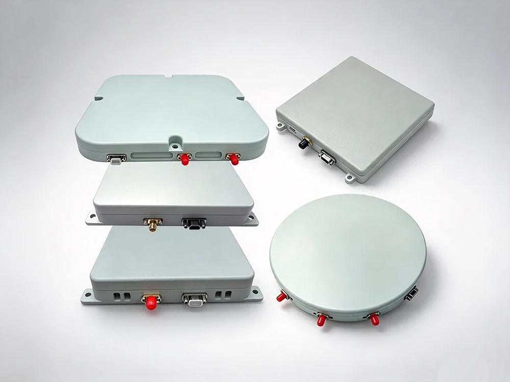
The first question is not “Which antenna has the deepest null?” It is “Where will the antenna sit, and what does that location do to the pattern?” Platform structure, ground plane, radome, cable routing, and nearby emitters can change performance more than a datasheet difference. A controlled reception pattern antenna that works well on a large vehicle may be a poor fit for a small unmanned platform or a fixed mast with limited sky view.
Selection criteria should include mounting area, weight, power and data cabling, connector type, environmental sealing, and whether calibration can be performed after installation. If the antenna cannot be installed and calibrated in the real configuration, its laboratory performance is not a reliable selection basis.
Filter 2: Match the Antenna Type to the Interference Problem
Anti-jamming antennas are not a single category. Fixed antennas with filtering, multi-element controlled reception pattern antennas, and beamforming arrays solve different problems. The table below gives a practical comparison for early selection.
| Antenna approach | Best suited to | Main selection checks | Limitations to plan for |
|---|---|---|---|
| Fixed anti-jam antenna with filtering | Low-SWaP platforms, moderate interference, cost-sensitive builds | Filter selectivity, out-of-band rejection, grounding, installation repeatability | Limited spatial nulling; performance depends on interference direction and platform |
| Multi-element CRPA | Directional or changing interference, platforms with space for an array | Element matching, calibration, nulling consistency, cable phase stability | Installation complexity, calibration effort, higher cost and power |
| Beamforming array | High-value platforms needing both nulling and gain toward satellites | Beam control, tracking behavior, integration with receiver | Larger size, processing complexity, platform-specific validation |
A useful rule is to select the simplest antenna architecture that meets the interference and installation requirements with margin. Over-specifying an array can add cost, calibration burden, and integration risk without improving mission outcomes.
Filter 3: Check Calibration and Installation Support
For multi-element antennas, calibration is not a paperwork item. It is part of the product’s usable performance. Ask how phase and amplitude errors are measured, how often calibration is needed, whether calibration data travels with the antenna, and how installation changes are handled after repair or replacement.
The supplier should provide a clear installation method, torque and grounding guidance, cable matching requirements, and a way to verify performance after installation. If the antenna requires a calibration service that the program cannot access in the field, that should be treated as a lifecycle constraint, not a minor support detail.
Filter 4: Verify with Tests That Resemble the Mission
Antenna selection should include evidence, not only specifications. Request test data for the installed configuration where possible. Useful evidence includes pattern measurements, nulling depth across relevant angles, performance with cable and radome installed, and behavior when interference changes direction.
The test plan should distinguish between antenna-only measurements and system-level checks with the receiver. An antenna that performs well in an anechoic chamber may behave differently when connected to a real receiver with its own filtering and tracking loops. Selection should therefore include a joint antenna-receiver test or a clear plan for one.
Filter 5: Treat Commercial and Lifecycle Factors as Selection Criteria
Price, lead time, warranty, repair, and obsolescence belong in the selection matrix, but they should not drive the first decision. A lower-cost antenna that cannot be calibrated or replaced in the field may cost more over the program life. Conversely, an expensive array may be unnecessary if the interference environment is modest and the platform cannot support calibration.
A Short Selection Worksheet
| Decision area | Question to answer before selection | Evidence to request |
|---|---|---|
| Installation | Where will the antenna be mounted, and what affects its pattern? | Installation drawing, platform test data |
| Interference | What directions, bandwidths, and durations must be tolerated? | Interference scenario, test report |
| Architecture | Is fixed filtering, CRPA, or beamforming actually needed? | Architecture trade study |
| Calibration | How will phase/amplitude be calibrated and maintained? | Calibration procedure, field support plan |
| Verification | How will installed performance be proven? | Test plan, chamber and system-level data |
| Lifecycle | How will repair, replacement, and obsolescence be managed? | Support agreement, lifecycle plan |
Bottom Line
Choosing an anti-jamming antenna is an installation and verification problem before it is a performance-number problem. Start with the platform, match the architecture to the interference, confirm calibration support, and demand test evidence from the installed configuration. Commercial factors matter, but they should filter the shortlist—not define it.